To remove the Rotary CAV DPA injection pump from Ford 3 and 4 cylinders
CAV Rotary Pump Removal for Ford 3 and 4 cylinder Tractors
To perform this task you will need
the following tools
½ inch wrench, 9/16 inch wrench, ½ inch socket with
extensions, 5/8 inch wrench, 5/16th inch wrench, Loc-tite, pliers,
putty knife or scraper screw driver and a tub or pan to catch water from the
radiator. The back mounting bolt on the pump flange can be easily reached with
a 90 degree ½ in wrench from the front, or a extension from the back, if using
an extension you may find it to be a little easier with a wobble or flexible
attachment on the end.
1. Remove the negative battery cable
2. Remove the lower radiator hose
3. Remove the plate on the front of the timing gear cover
directly in front of the injection pump, there are 5 bolts in most of these, it
will also be required on some units to remove the Valve cover vent pipe
(Fig 1)
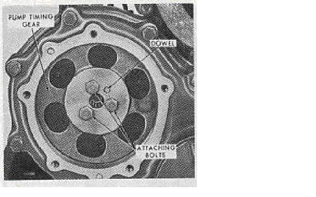
4. After the front cover is removed you will be looking at 3
bolts as pictured above,(fig 1) it may be a good idea to lay a paper towel in the
bottom between the gear and the cover, to prevent any thing that is dropped
from getting into the timing gears.
5. Remove the 3 bolts taking extreme caution not to drop them.
6. After the bolts are removed clean the mounting area
pictured below
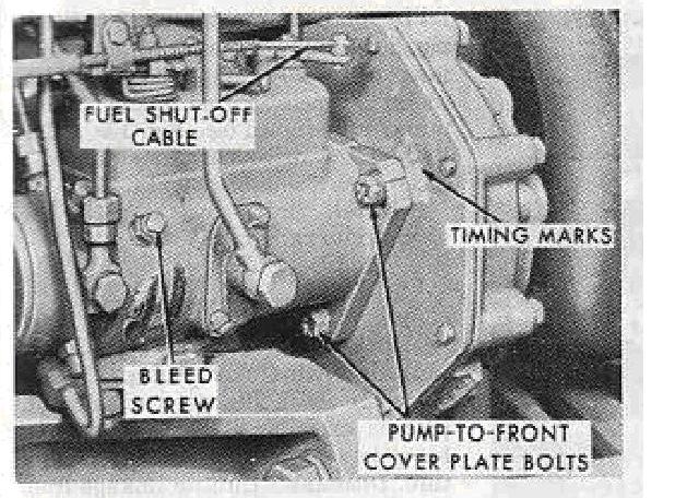
7. Check the timing marks, in fig 2, if they are not in line
take a small chisel and strike a mark on each surface that will be in line.
(Fig 2)
8. Turn the fuel supply off if you have not already done so.
9. Remove all lines going to the pump,
The lines going to the injectors it
is a good idea to mark them in a way you can remember which line goes where.
The front injector (nearest the radiator will be #1.)
10 Remove the throttle and shut off linkage, make certain to
leave the levers attached to the pump
11 Now you are ready to remove the pump to front cover
mounting bolts pictured in (fig 2). There are 3 bolts start by removing the
hardest one to reach first. It is not seen in the picture.